Vertical test furnace
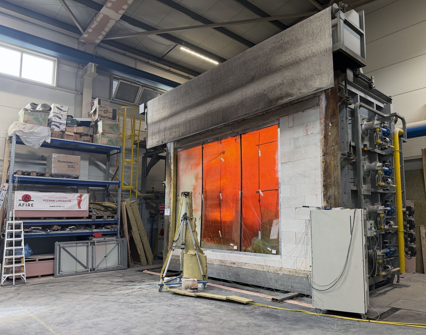
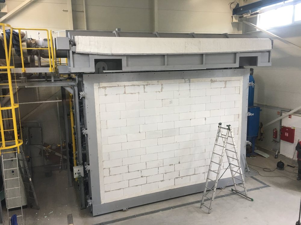
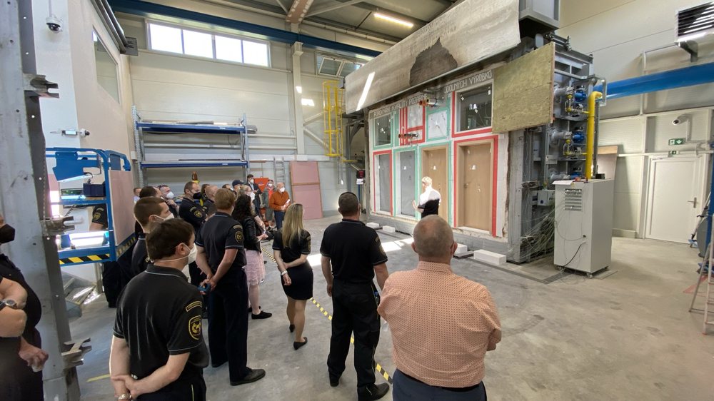
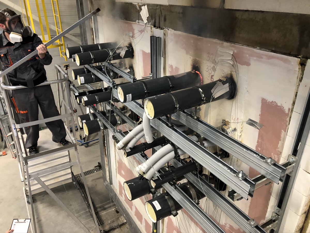
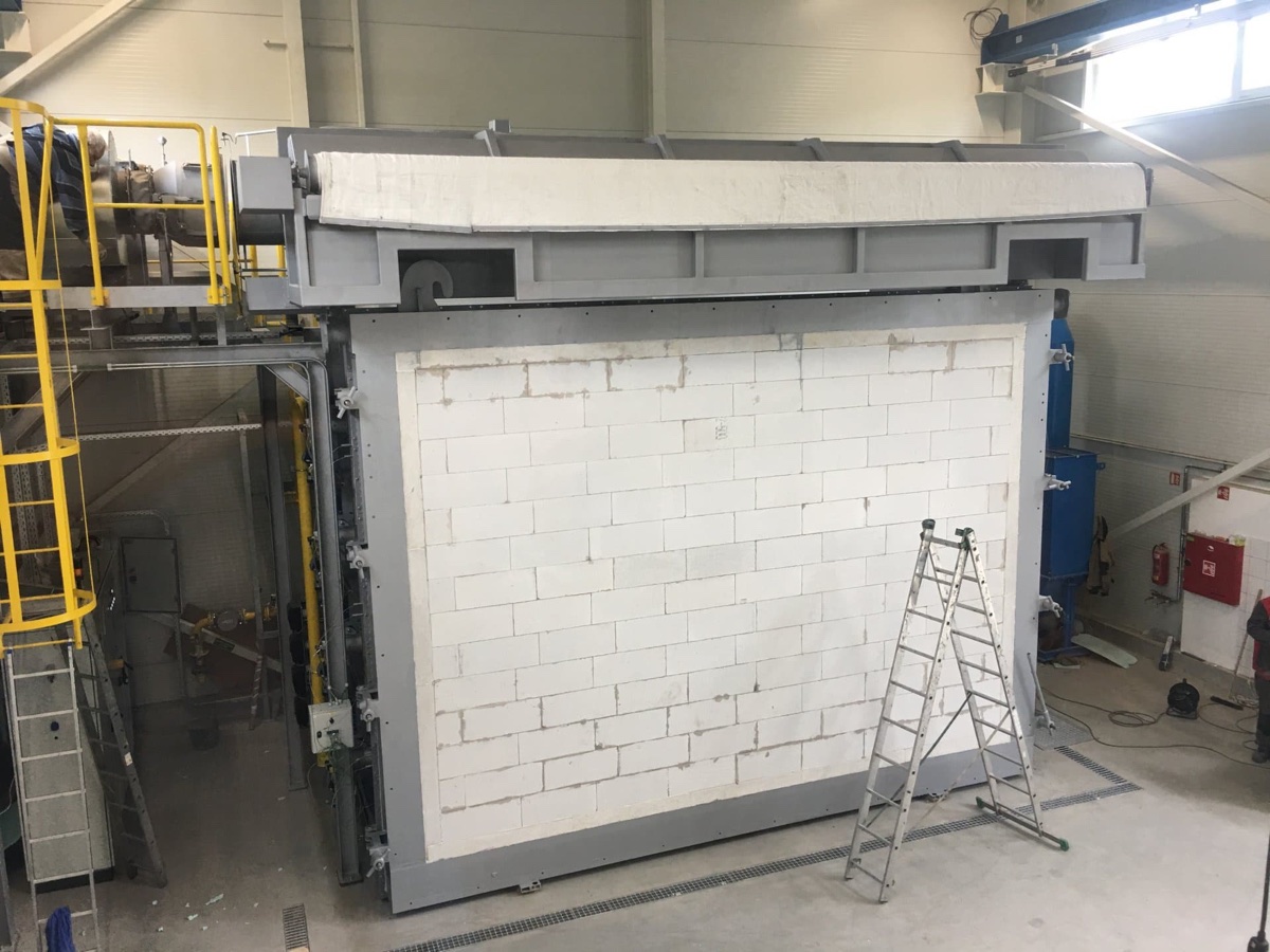
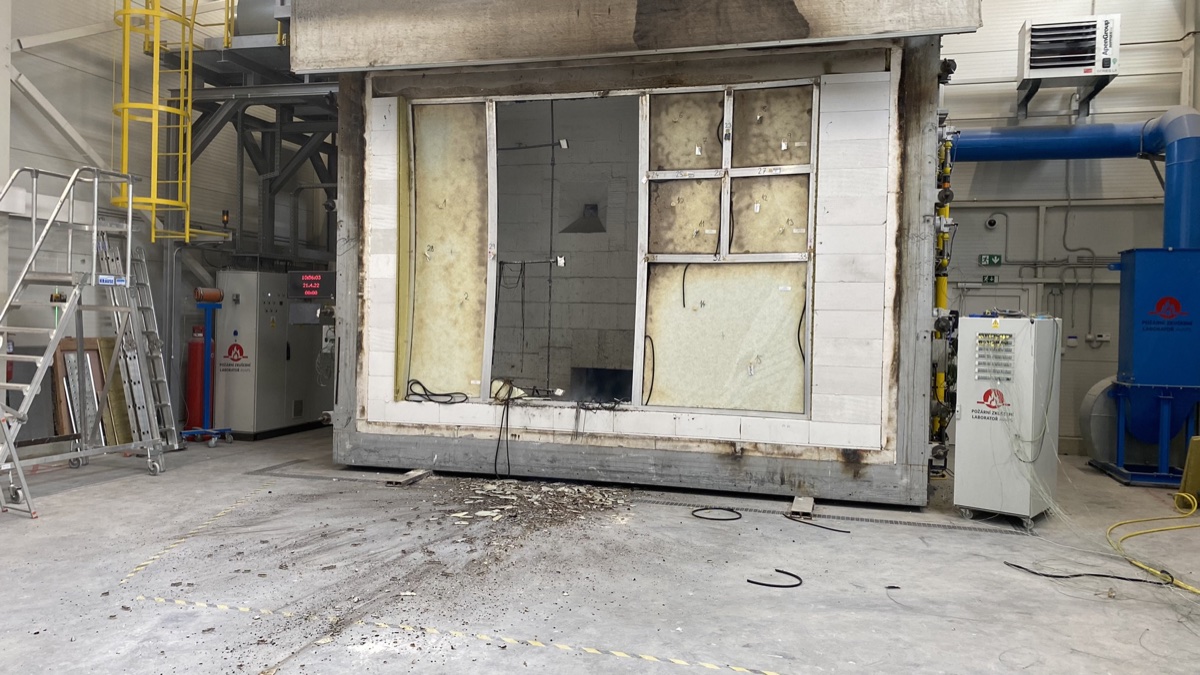
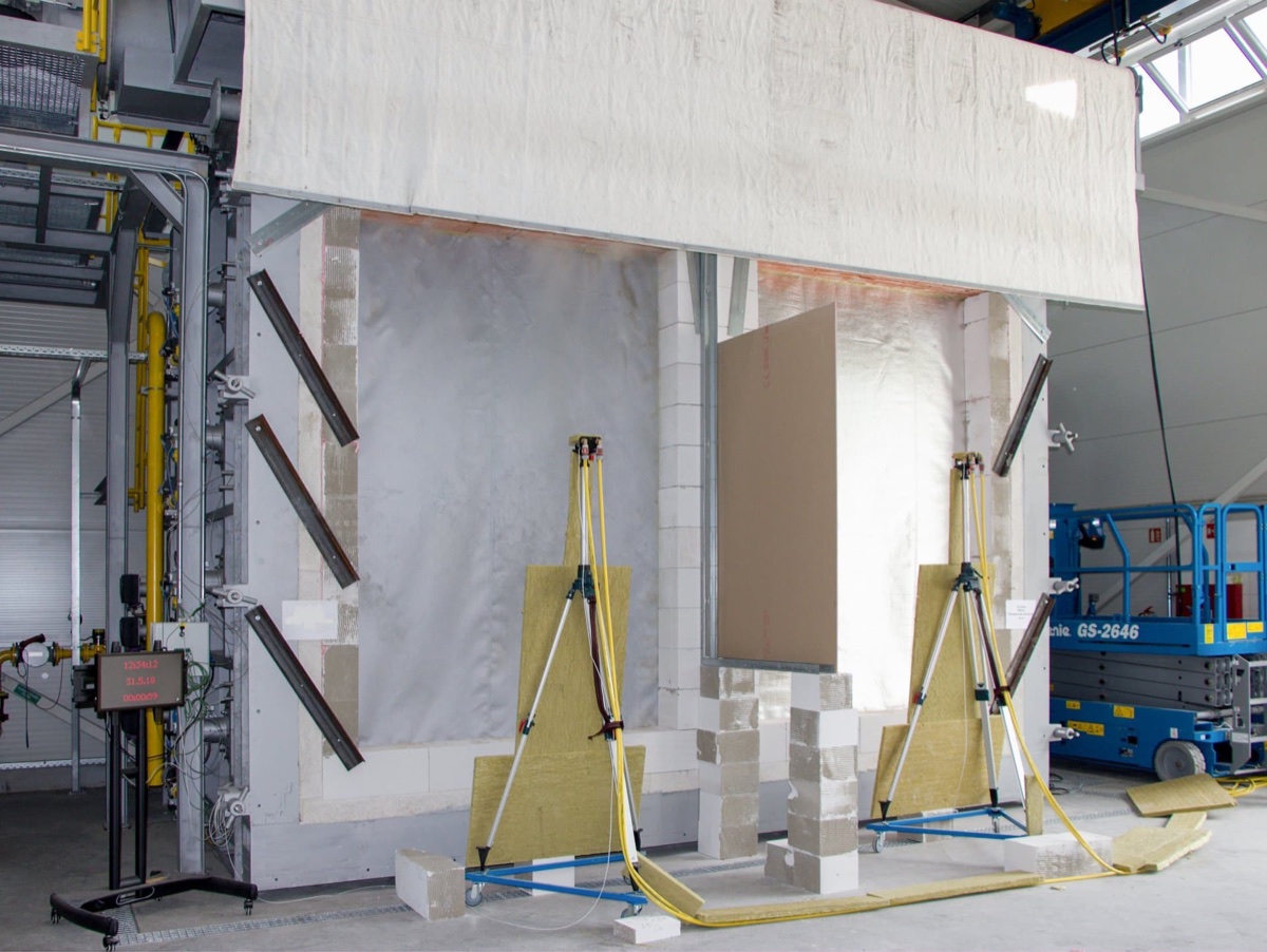
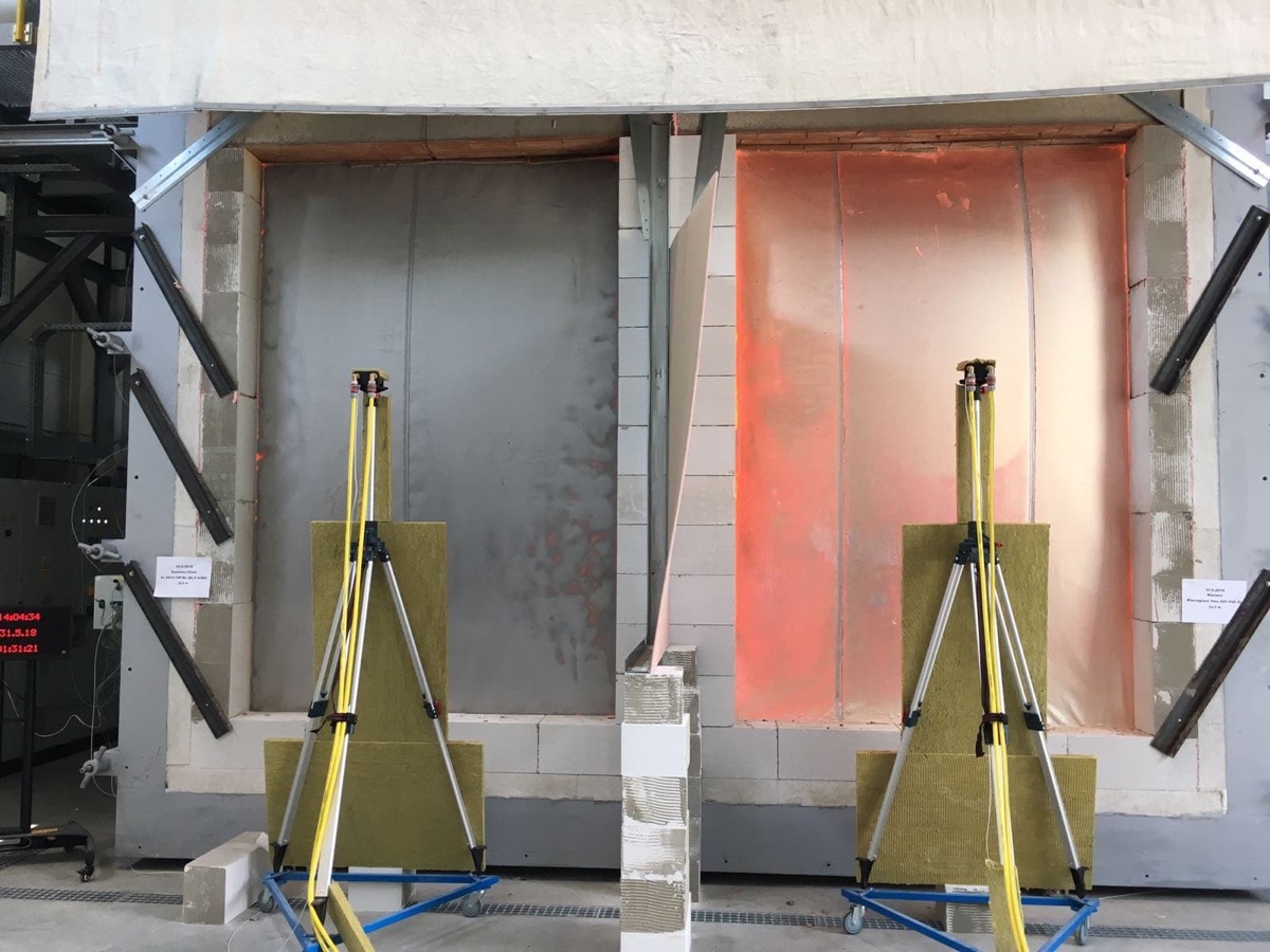
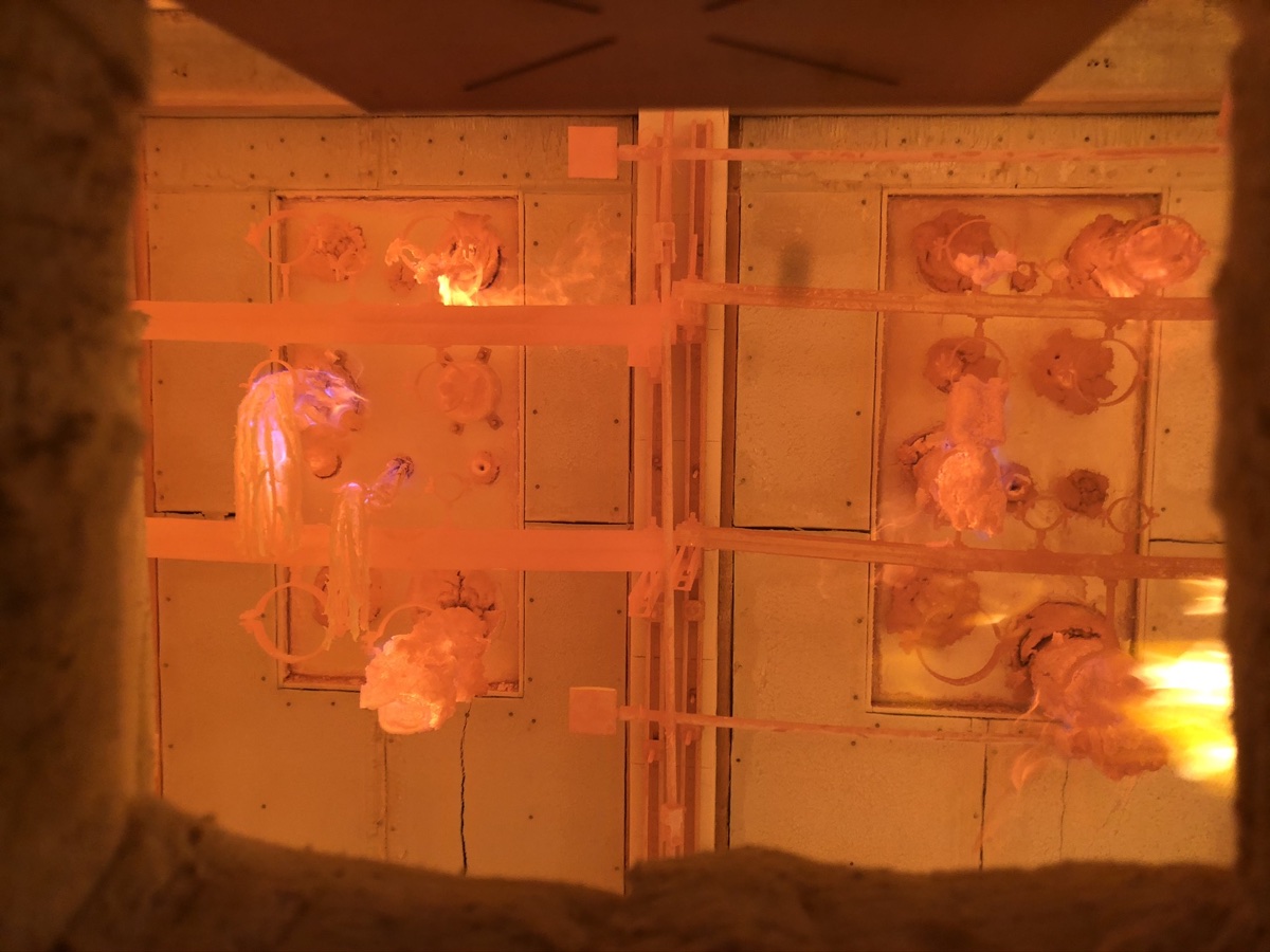
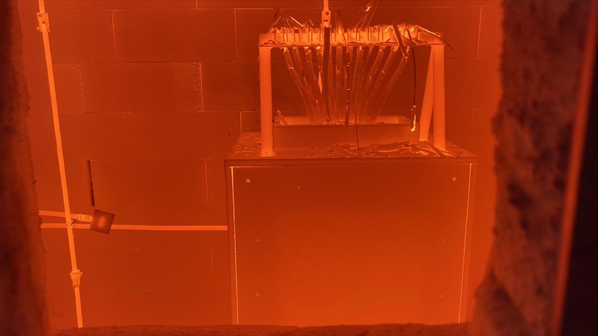
The furnace is intended for fire resistance tests of non-load-bearing wall structures and other elements in non-load-bearing test frames. It meets the requirements of the relevant test standards as part of the accreditation and enables accurate and repeatable measurement of the temperature course and the monitoring of the behaviour of materials, products and structures in a fire.
Furnace capabilities
- maximum dimensions of the test space (5.0 x 3.5 x 1.8) m (W x H x D),
- non-load-bearing test frames for testing non-load-bearing structures,
- tests lasting up to 300 minutes,
- overhead crane with load capacity 12 tons and scissor work platform GS-2646 for mounting large samples,
- adequate equipment complying with the requirements of European test standards.
Controlled fire, accurate measurement
3.6 MW of heating power
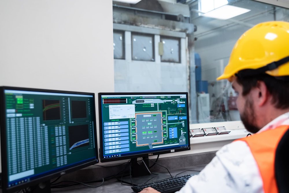
Eight high-speed gas burners allow temperatures of up to 1,187°C to be reached. The computer controls the output so that the actual temperature-time curve follows the prescribed temperature curve within the tolerances established by the test method.
More types of temperature curves
In addition to the most common standard curve, it is also possible to test according to the curve of external fire, slow heating or hydrocarbon curve.
More about temperature curves →Hundreds of data points
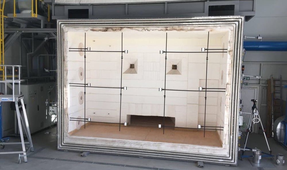
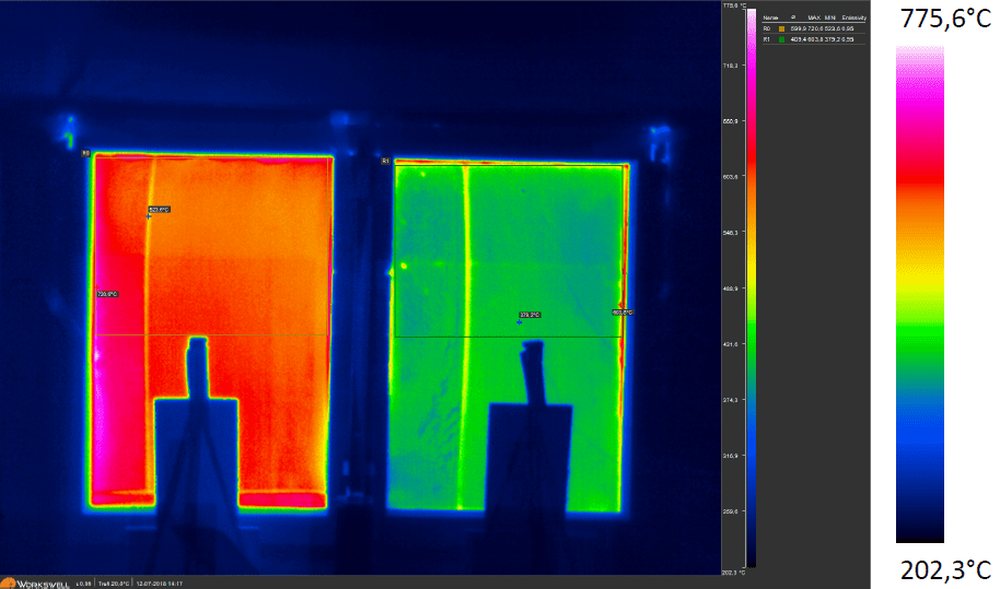
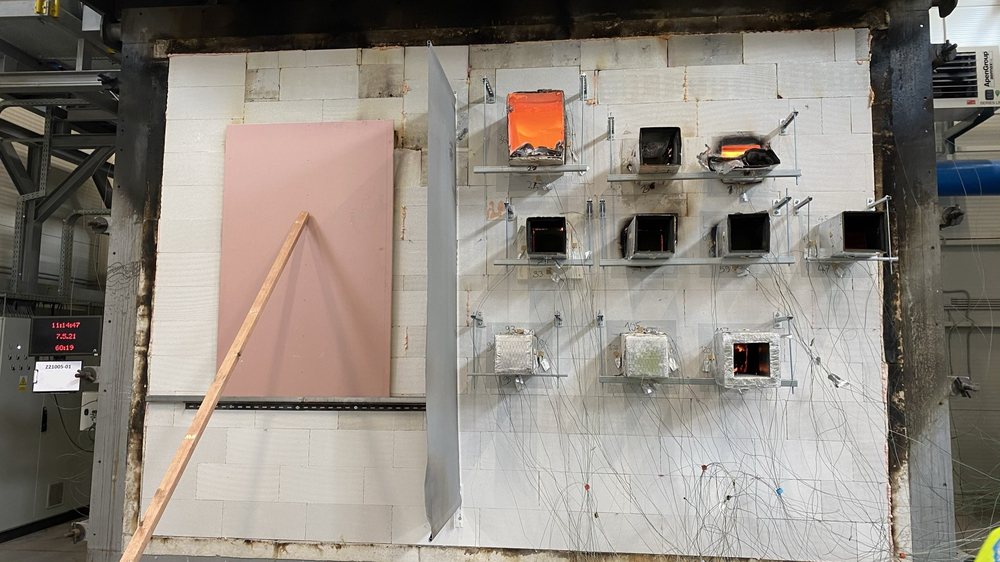
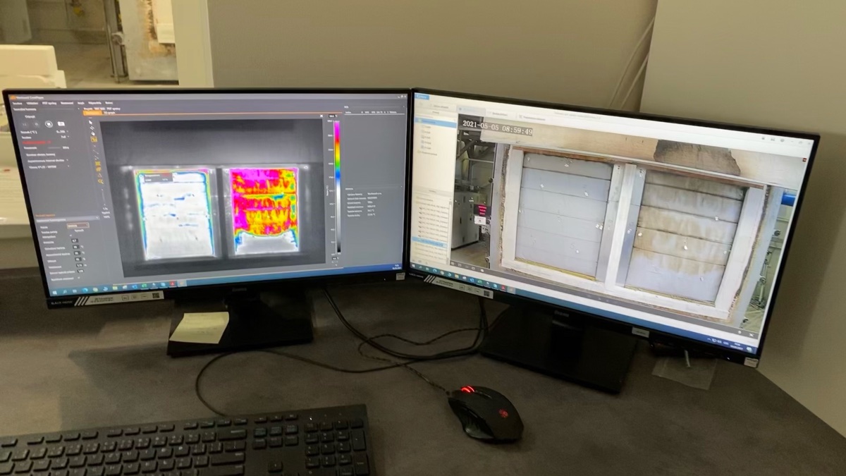
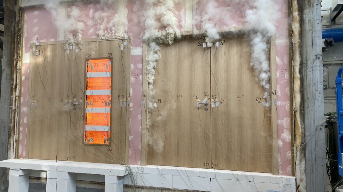
Up to 200 thermocouples can be connected simultaneously. Depending on the purpose of the test, the basic measurement can be supplemented with the measurement of the radiant heat flux for classification W and recording with a thermal camera.
You can watch the test live
The progress can be streamed online via webcam. Thus, the client can monitor the behaviour of the sample without being personally present in the laboratory.
We can control the fire, accurately measure it and back it up with data.
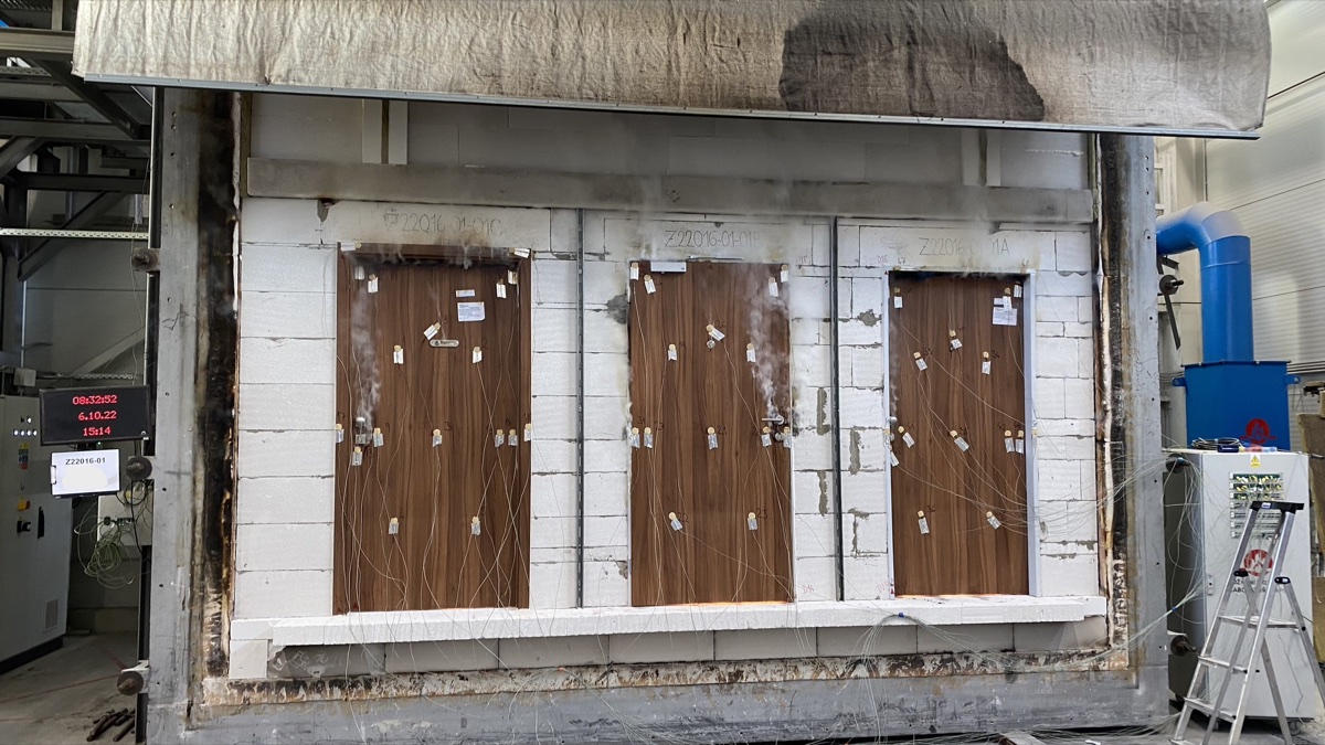
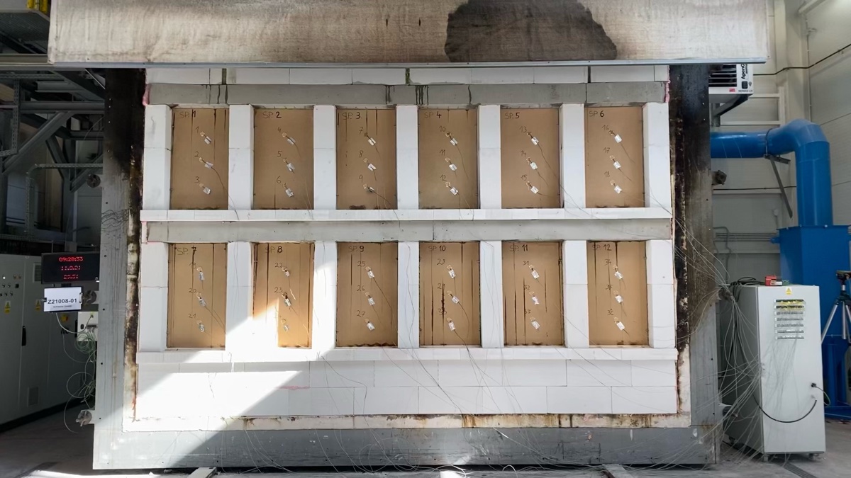
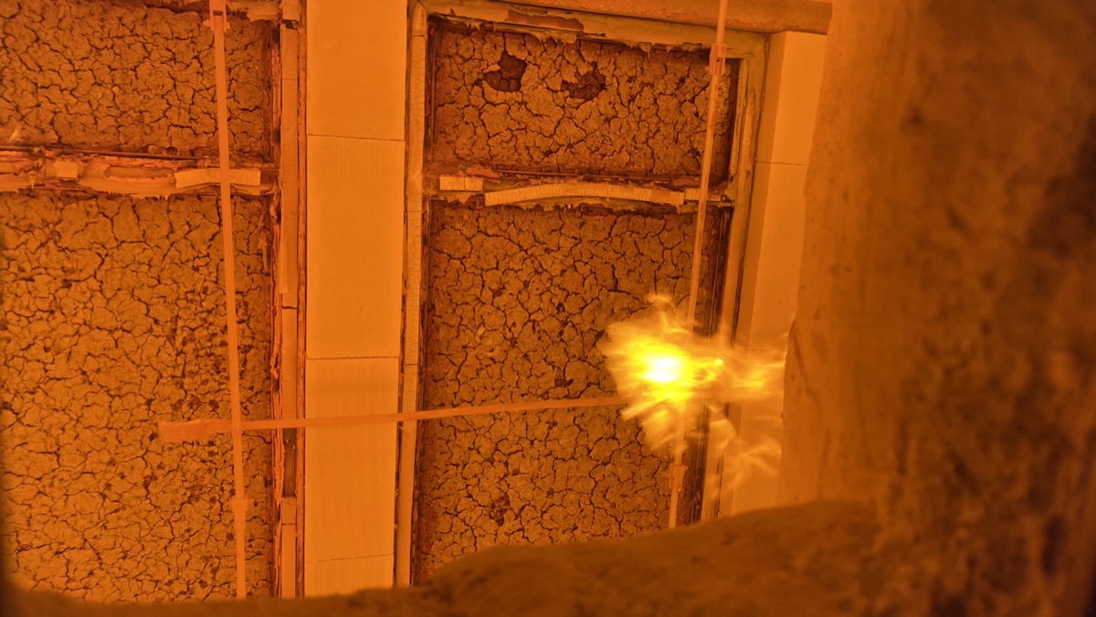
From our tests
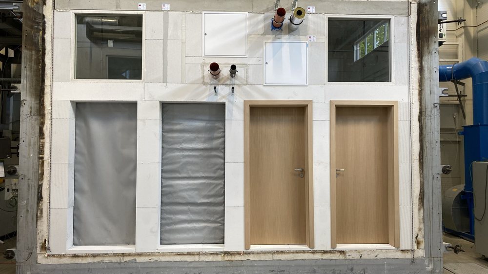

Drawings for download
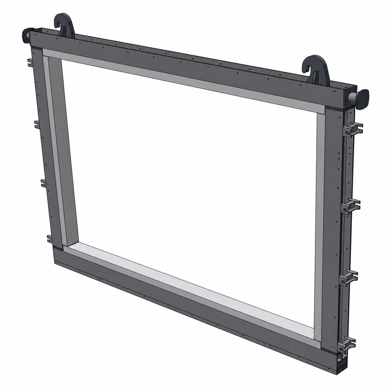
To prepare for the test, you can download a sample thermocouple layout and a drawing of the test frame. The materials will help you design the sample and plan its placement.
PDF
Distribution of thermocouplesSample of measuring points during the test
 PDF
Drawing of the test frame
PDF
Drawing of the test frameDimensions and design of the sample mounting frame
For more documents, see the section For download. We will send you a drawing in DWG format upon request.
Do you need a fire resistance test?
Tell us the parameters of the sample — we will suggest the procedure and the deadline.